
RTM-Worx User Manual
Mesh generation
3.2 Mesh Generation
3.2.1 FEM Mesh basics
3.2.2 Controlling mesh generation
3.2.3 Optimizing mesh and geometry
RTM-Worx subdivides the part defined with surfaces, curves and keypoints into so-called elements and nodes, which form the basis for the Finite Element Method. You don't need to be a FEM expert to use RTM-Worx. Everything (and probably even more than) you need to know is provided in this manual.
![[top]](../asp/tp.gif) 3.2.1 FEM Mesh basics
3.2.1 FEM Mesh basics
RTM-Worx uses the mesh for two purposes:
- The main purpose is the calculation of flow of resin and to track the part of the mold that is filled and the part still empty. Pressures are solved in the element vertices, so called nodes, and from the pressures the resin velocities can be calculated on the elements.
- Display of the model is done by displaying the elements in the FEM mesh. This allows the seamless integration of pre- and post processing and also gives visual feedback regarding the accuracy of the approximation of the actual geometry.
Because editing is interactive, and any changes to the geometry must be shown the mesh always needs to be defined for all geometry objects. This is taken care of by an incremental mesh generator that subdivides curves into edges and surfaces into triangles only when they have been modified. The mesh generator is invoked automatically by the geometry editors when you add or modify the model. However, to be able to control the size of the elements and set the meshing parameters, the Mesh generator Control panel is available.
The relation between mesh size and calculation accuracy is easy to understand: using more and smaller elements increases the accuracy of the results but also increases the calculation time. The number of elements you need for a given accuracy depends on the geometry of your part and the way it is injected.
- Pressures are calculated in the nodes and assumed to vary linearly on the elements.
- The location of the flow front is traced by recording the filled fractions of the nodes.
For example, in the neighborhood of single injection points, the pressure is a logarithmic function of the distance to the injection point which is difficult to capture with a piecewise linear approximation on a coarse mesh and you need small elements to get an accurate estimate of the pressure gradient, velocities and the filling time. On the other hand, if you use a line gate (several injection points at adjacent nodes on a curve, or with a connector element) the pressure gradient is linear and calculated exactly even on very coarse meshes.
Each node in the mesh is assigned a volume, which is the sum of a part of the elements connected to the node (half the volume of a runner element and approximately one-third of the volume of a triangular shell element). You can view the subdivision in Nodal Control Volumes (complementary to the mesh) by toggling the Render|Control Volumes menu switch or the equivalent button on the Render toolbar. During filling of the mold, the filled fraction of each Nodal Control Volume is used to track the filled part of the mold (100%), the empty part of the mold (0%) and the location of the flow front (filled fraction in between 0% and 100%). The pressure calculation is only done for completely filled nodes and the pressure in the front nodes is set to zero. Therefore, the approximation of the location of the flow front becomes more accurate when a finer mesh is used that contains more nodes.
In addition, the shape of the triangular shell elements influences the accuracy of the calculation. Ideally, the triangles are equilateral (all sides equal length with three internal angles of 60 degrees), and obtuse triangles (with one internal angle that is larger than 90 degrees) should be avoided whenever possible. The source of inaccuracy related to the element shape can be attributed to the following:
- Accuracy of the pressure calculation becomes dependent on the direction if elements are used with sides that have different lengths. Of course, this is only relevant when pressure varies a lot on the element and if this variation is non-linear.
- Triangular elements are subdivided in parts for the Nodal Control Volumes by three lines perpendicular to the sides as long as the intersection point is on the element. This is not true for obtuse elements, so that the midpoint on the side opposite to the obtuse corner has to be used.
- The filling time in each node is calculated as the time at which the associated Control Volume is 50% filled. This is very accurate if the node is properly centered in the elements it is connected to, but becomes inaccurate when element size or shape varies a lot.
Two types of shaded plots are provided to visualize the quality of the mesh:
- Obtuse triangles: shading is proportional to the angle of the obtuse corner. Generation of a few obtuse triangles that have a corner slightly larger than 90 degrees is acceptable and generally unavoidable.
- Element quality: shading color proportional to size of smallest element edge divided by the size of the largest element edge. This value should be as close to 1.0 as possible.
Because the accuracy of the simulation depends on many factors, accurate estimates of the error or rules that are easy to follow cannot be given. The best way to find out if the mesh is accurate enough is to repeat the calculation with a smaller mesh size and compare the results.
3.2.2 Controlling mesh generation
The mesh generator Control Panel contains four parameters to control the generation of the mesh and a set of buttons you can use to quickly change the mesh size and to remesh the model.
The size of the elements generated is controlled by the global minimum and maximum limits 'Min' and 'Max' and locally by the length of the curve segments, e.g. the amount of detail. If you do not define bounds on the mesh size (set Min to zero and Max to anything larger than the model size) a graded mesh is generated with a mesh size that is defined in keypoints as the shortest curve connected to the keypoint and interpolated in between the keypoints on curves and the surface boundaries. Because the mesh size locally changes during editing of the model and the incremental mesh generator only partially (re-) builds the mesh, it is always recommended to remesh the whole model before running a simulation after you made changes to the geometry. Just use the [Apply] command in the Mesh generator Control panel.
At the top of the Mesh generator Control panel, a few model statistics are provided to help you select working lower and upper bounds. The most common operations are implemented in the set of six buttons. Actually, each button modifies Min, Max or both and does a complete remesh of the model.
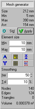 |
Model statistics. Size is the diameter of the smallest sphere that fits around the object. Min and Max are the lengths of the smallest and largest curve segment and Avr is the average curve segment length. |
| [Std] generates an unbounded mesh, [Apply] regenerates the mesh. | |
| Min and Max are the upper and lower bound respectively for the size of edges generated. You can enter values manually, or use the set of buttons below to use common settings or quickly change them. | |
| [Larger] doubles lower bound, [Coarse] creates a mesh with a minimum of elements and [Equal] assigns current upper bound to lower bound. [Smaller] halves upper bound, [Uniform] sets upper and lower bounds equal to smallest edge and [10%] sets the upper bound to 10% of Size. | |
| Mesh smoothing parameters influence the final quality of the mesh which is generated in two stages, of which the second stage improves element quality by edge swapping and repositioning of nodes. | |
| Mesh statistics: number of FEM nodes (including nodes generated at keypoints), number of edges
(on curves and runners only) and triangles. The volume is calculated from the current mesh in combination with specified properties. |
Use the [Coarse] command to generate a mesh with as few triangles and nodes as possible. The [10%] command is a good starting point.
The mesh size is easily changed by using the [Larger] and [Smaller] buttons which double the lower bound and halve the upper bound respectively. Repeated use of those buttons will result in equal upper and lower bounds.
For best results, all elements should have about the same size. The [Equal] button generates such a mesh by using an upper and lower bound both equal to the smallest edge in the geometry. This often generates a lot of elements however.
The mesh is built in two stages. The first stage generates the triangles, edges and nodes. This 'raw' mesh is smoothed in the second stage where edges are swapped to remove as much obtuse triangles as possible and nodes are centered in between adjacent nodes. This is an iterative process, and you can control the maximum number of iterations and the tolerance in the 'Iter' and 'Tol' fields respectively. The default values work very well on flat and mildly curved surfaces, but you might want to increase the number of iterations and lower the tolerance for strongly curved surfaces.
3.2.3 Optimizing mesh and geometry
In the previous sections, the relation between mesh and accuracy was detailed and the methods to influence the mesh size were described. The most difficult part is to decide how much detail to include to get results that are accurate enough to be representative for the actual flow so that you can use the simulations to optimize injection of the product. Here are a few guidelines:
- Use as few curves, surfaces and keypoints as possible to give the mesh generator maximum freedom to generate elements of optimal shape and avoid generation of obtuse triangles.
- Do not include details that have a size equal to or smaller than one element. It is generally a good idea to start with a rough approximation of the geometry of your part. You can run a simulation to verify the correctness of the model and gradually add details. This will also provide good insight in the influence of those features to the overall flow and the way the part fills.
- Be careful if you want to locally force the generation of smaller elements by adding keypoints. Especially if you want to repeat the calculations on a coarse mesh, the small distance between existing and added keypoints might lead to the generation of badly shaped triangles. It is often a better solution to reduce the element size by decreasing the 'Max' upper bound on the edge size.
- Use a mesh with about 500 to 1000 elements to run most of your simulations. The calculation will be very fast, and the accuracy is sufficient to optimize the location of injection and venting ports. Finish with a number of simulations for the most promising alternatives with a refined mesh
![]()
home |
contents |
about this manual |
quick start |
introduction
installation |
features |
philosophy |
getting started |
interface |
workspace
menu and commands |
viewing the model |
model and calculation
geometry and properties |
simulation
© 1997-2022 Polyworx
![[home]](../asp/pwxpwx.gif)