
RTM-Worx User Manual
Menu and commands
2.2 Menu and Commands
2.2.1 Menu overview
2.2.2 Project menu
2.2.3 View menu
2.2.4 Simulation menu
2.2.5 Render menu
2.2.6 Tool menu
2.2.7 Help menu
Like (almost) all Windows applications, RTM-Worx has a menu, which is accessible through the bar just below the window title. In this section the menu and the menu commands will be explained in detail.
![[top]](../asp/tp.gif) 2.2.1 Menu overview
2.2.1 Menu overview
The RTM-Worx menu is shown below. Most of the menu commands are also available in toolbars, and some in Control Panels. To make it easier for you to learn to use the toolbars, the same images that are used on the buttons are also displayed in the menu.
| Project | View | Simulation | Render | Tool | Help | |||||
| New | Toolbar | Run | Redraw all | Select | Help Topics | |||||
| Open | Statusbar | Restart | Background plotting | Zoom | What's This? | |||||
| Rename | Renderbar | Clear | Shrink elements | Rotate | Using Help | |||||
| Copy | Model view | Keypoints | Pan | About | ||||||
| Archive | Appearance | Curves | Squeeze | |||||||
| Import | Plot selector | Surfaces | Scale | |||||||
| Exit | Keypoint editor | Edges | ||||||||
| Curve editor | Control Volumes | |||||||||
| Surface editor | Gates | |||||||||
| Mesh generator | Markers | |||||||||
| Simulator | Runners | |||||||||
| Pipes | ||||||||||
| Shells |
A short summary of the functionality available in each submenu is:
| o | Project | File operations; import files from other applications; quit RTM-Worx. |
| o | View | Show, or hide, toolbars and statusbar; select Control Panel. |
| o | Simulation | Run the simulation and clear results. |
| o | Render | Control plotting and select objects and/or parts of the model to display. |
| o | Tool | Select function of the mouse in the display area and some miscellaneous global modeling functions. |
| o | Help | Access to online help, context-sensitive help and program information. |
The commands in the menus will be explained in detail in the following paragraphs.
![[top]](../asp/tp.gif) 2.2.2 Project menu
2.2.2 Project menu
The project menu contains the commands for file operations and to quit RTM-Worx. This menu is called the 'File' menu in most applications, but it has been renamed to reflect the slightly different way RTM-Worx deals with files.
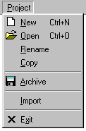 |
Start a new project (closes current project). |
| Load a new project from disk (closes current project). | |
| Change the name and/or location of the current project file. | |
| Create a (snapshot) copy of the current project. | |
| Archive the current project into an ARX (read-only) file. | |
| Import a model from a CAD, STL or FEM file.. | |
| Close RTM-Worx, save current project and configuration. |
The most important rule to remember is:
There is no difference between what you see on screen, what is loaded in memory or what is stored on disk.
Any changes are saved to disk (not necessarily immediately when you make them). If you want to keep a copy (snapshot or milestone) of your current model, you have to create one before you make any changes. Once you understand the concept, the menu will make sense.
If you start a new project with the Project|New command, RTM-Worx automatically generates a name. You can rename the project with the Project|Rename command or edit the name in place.
Load an existing project with the Project|Open command which displays a dialog where you can select the file. You can also use Windows Explorer: double-clicking the filename will load the project.
The Project|Rename command can be used to change both the project name and the location of the project file and it does not create a copy (like the Save as... command in other applications).
Use the Project|Copy command if you want to save a temporary copy of the current project which may also be used to start another project. The file name of the copy is automatically generated: it starts with 'Copy(x) of' followed by the name of the current project. The 'x' is a number that is automatically incremented if you create more than one copy of the project.
If you want to save a milestone copy of your project, typically a worked out case with simulation results, use the Project|Archive command to create an archive file. This is a file with the same name as the project file but an ARX instead of a WRX extension and a version number that is automatically incremented. If you open the archive, RTM-Worx creates a WRX file for the project and does not change the contents of the archive. Archiving this project will add a new numbering level for the ARX files. This hierarchical numbering scheme makes it very easy to maintain the different versions of your model, because it shows both the order and the heritage of the files.
You can import geometry and, depending on the type of file, properties from STL (both ASCII and binary formats), AutoCAD DXF, C-Mold™ FEM, p7 PI7 and Sepran MSH files. RTM-Worx will convert CAD entities and FEM nodes, edges and elements into geometry objects. This makes it possible to modify the imported model, but may lead to a huge number of surfaces, edges and points. The completeness of the model depends on the type of file and it's contents.
NOTE: The current model will be deleted before the file to import is read into the current project. Start a new project or save the current project into an archive before you import the file.
![[top]](../asp/tp.gif) 2.2.3 View menu
2.2.3 View menu
The view menu contains commands that affect the visible parts of the RTM-Worx window.
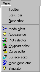 |
Show main toolbar (below the menu), status bar (bottom of RTM-Worx window) and render bar (below display area) when checked. |
| Select the Control Panel.. The Model view Control Panel contains controls for accurate definition of view direction, scale, perspective distortion and z-clipping plane. Light, color and model/object reflection properties are set in the Appearance control panel. Select properties and/or results for contour, shaded and vector plots in the Plot Selector Control Panel. The geometry can be edited in the Keypoint, Curve and Surface editors. Use the Mesh generator to control size of elements and to remesh the model. The Simulator Control Panel contains the commands to run the simulation, calculation control parameters and the resin properties. |
Switching the Control Panel is something you will do a lot. Therefore, the commands to select the Control Panel are all duplicated in the main toolbar.
If you want to run the simulation and you don't need to change resin properties or calculation parameters, you can use the Simulation menu (see next paragraph) or the keyboard accelerators instead of switching to the Simulator Control Panel, which saves some time and mouse clicks.
![[top]](../asp/tp.gif) 2.2.4 Simulation menu
2.2.4 Simulation menu
The simulation menu contains the three basic commands to run the simulation. You can also find those commands in the Simulator Control Panel.
 |
Run the simulation: continue from currently selected time step. |
| Clear results, and run the simulation. Always starts at t=0. | |
| Clear results. Useful to reduce the database size. |
The fastest way to rerun the simulation when you made some changes is to hit the F9 key. Note that your results are automatically cleared when changes to the model (geometry or properties) were made.
![[top]](../asp/tp.gif) 2.2.5 Render menu
2.2.5 Render menu
This menu contains the commands to control plotting and selection of objects and/or parts of the model to display. All the commands are available in the Render toolbar (below the display area).
RTM-Worx redraws the model automatically. Because this is a time-intensive task, this is done as a low priority background task. Plotting is sometimes not completed, typically when the database is being updated and the renderer has to wait too long to get read access. When this happens, you can always use the Render|Redraw all command to fix this.
If you want to animate the filling process, check Render|Background plotting. The image will be rendered in an off-screen buffer and displayed when this has finished which avoids flickering of the image.
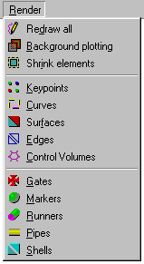 |
Do a full redraw. Useful when plotting was aborted. |
| Render model in the background. Display when finished. | |
| Shrink 3D shell elements, runners and curves. | |
| Display keypoints, gates and venting ports as flat squares. | |
| Wireframe plot: show curves and runners as lines. | |
| Hidden surfaces (minimum requirement for shaded contours). | |
| Show edges of Finite Elements on surfaces, curves and runners. | |
| Display subdivision of elements into Nodal Control Volumes. | |
| Plot injection and venting ports as 3D symbols. | |
| Plot keypoints as symbols, injection and venting ports excluded. | |
| Show runners as 3D pipes, using their actual diameter. | |
| Display curves as 3D pipes (diameter equals symbol radius) | |
| Plot shell elements as 3D prisms, using their actual thickness. |
Checking Render|Shrink elements will shrink 3D runners, curves and shells. It does not affect the display of flat surfaces and lines; while triangles drawn by element edges are always shrunken.
When you select curves or runners that are displayed as lines (not as 3D objects) they have an imaginary diameter that equals the point size. The same is true for element Edges and Control Volumes (you may wish to turn them off to be able to select curves).
Runners with a zero diameter are always displayed as lines. If a surface has a zero thickness, it is only displayed when Render|Surfaces is checked, it will not display if Render|Shells is checked. This is useful to verify if you assigned properties to all surfaces.
![[top]](../asp/tp.gif) 2.2.6 Tool menu
2.2.6 Tool menu
The tool menu contains commands to select the function of the mouse in the display area and some miscellaneous commands that affect the model as a whole.
In all modes, the mouse cursor changes its shape, depending on the currently selected tool. In Zoom, Rotate and Pan mode, the effect of clicking or dragging the mouse depends on the position in the display panel and whether the Ctrl key is down or not, which is also indicated by the mouse cursor.
In selection mode, parts of the model that can be selected at the current mouse position are plotted with inverted colors.. This is indicated by the mouse cursor. The selection function only works in the geometry editors (keypoint, curve, surface). In other Control Panels, the selection is turned off.
The Tool|Squeeze command renumbers all keypoints, curves and surfaces sequentially, starting at 1. This removes the gaps (unused numbers) that typically result after extensive editing of the model.
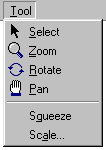 |
Select points, curves and surfaces with the mouse. |
| Use the mouse for dynamic rotation of the model. | |
| Zoom with the mouse, define rectangle or dynamic by dragging. | |
| Dynamic panning (scrolling) and adjustment of the z-clipping plane | |
| Renumber geometry object sequentially without gaps. | |
| Scale the geometry, including shell thickness and runner diameter. |
The Tool|Scale command gives you the possibility to change the absolute size of the geometry, while the relative size including shell thickness and runner diameter does not change. Originally part of the code to import models from files without length units (e.g. STL), it is now available as an independent command, making it much more powerful.
![[top]](../asp/tp.gif) 2.2.7 Help menu
2.2.7 Help menu
Through the Help menu commands (or the corresponding buttons on the main toolbar) you can access the online-help system. RTM-Worx provides extensive context-sensitive help. Use the Help|What's This? command to turn the cursor into an arrow plus question mark and click on anything you want help for. You will get a short description in a pop-up window that contains links to other topics in online-help.
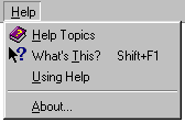 |
Launch online-help with Contents, Index and Find tabs |
| Enter context-sensitive help mode | |
| Get general information about using online help | |
| Information about RTM-Worx (version and copyrights). |
The Help|Using Help command opens the WINHELP.HLP file that is part of the Windows installation. If any error occurs, verify that this file exists on your system and is not corrupted.
home |
contents |
about this manual |
quick start |
introduction
installation |
features |
philosophy |
getting started |
interface |
workspace
viewing the model |
model and calculation |
geometry and properties
mesh generation |
simulation
© 1997-2022 Polyworx
![[home]](../asp/pwxpwx.gif)