RTM-Worx Overview
Mesh generation
Mesh generation
 Because RTM-Worx uses the Finite Element Method (FEM) to calculate pressures combined with a
Control Volume Method (CVM) to track the flow front, the geometry has to be divided into line
elements on runners and triangular elements on surfaces. During construction of the model, each
curve and surface is meshed automatically. This incremental meshing method is made possible by a
very fast mesh generator (approximately 8000 triangles per second on a Pentium 4 1.7 GHz). The
size of the elements governs the accuracy of the filling simulation and the accuracy in which
curved lines and curved surfaces are approximated. By default, the size of the elements is adapted
to the distance between keypoints, which leads to the generation of a so-called 'graded'
mesh. The element size can be influenced by the following parameters:
- Minimum element size. This is used as a lower bound and can be used to force generation of larger and less elements in the neighbourhood of very small details.
- Maximum element size, an upper bound that is used to generate smaller and more elements to increase the accuracy of the calculation.
You can create graded meshes by adding keypoints (easily done with the 'curve split' function) where you want smaller elements. Although this scheme has a high flexibility, in practice analysts experiment a lot with mesh generation but always end up choosing from a limited set of options. Therefore, RTM-Worx provides following push buttons:
- Coarse mesh. Generate minimum number of elements, as large as possible.
- Uniform mesh. Leads to generation of elements that are all approximately equal in size.
- 10% of model. Defines the maximum element size as 10% of the radius of the imaginary sphere in which the full geometry will fit. Good trade-off between accuracy and speed.
- Double minimum size. Increases the size of the smallest elements.
- Halve maximum size. Decreases size of largest elements, generates more elements.
Because of the robustness of the calculation, your only concern will be the accuracy, which is easily verified by repeating the calculation with different mesh sizes.

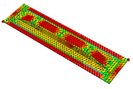
In the example plot above, surfaces are plotted 3D using their thickness and elements are visualised by shrinking them (80%). The colours indicate element quality: ratio of lengths from shortest edge and longest edge. Red is best and corresponds to a ratio of 1 (equilateral triangles), green is average and blue is worst (in this case ratio about 1/3).
home |
introduction |
requirements |
user interface |
geometry editor
material and process data |
pre- and postprocessing |
file system |
calculation
© 1997-2022 Polyworx
![[home]](../asp/pwxpwx.gif)