RTM-Worx Overview
User interface
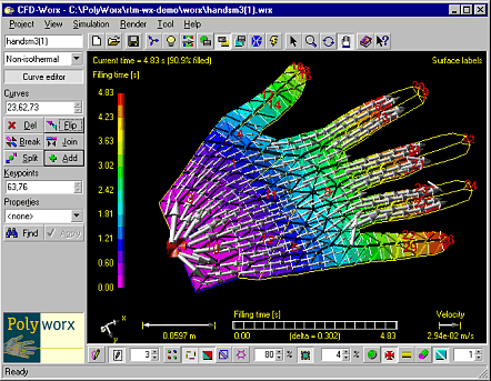
The RTM-Worx visual user interface
Central to the design of RTM-Worx is the environment in which all the tools you need are positioned around the display of the model and in which pre- and postprocessing are fully integrated.

All viewing and plotting options are always available. Buttons, edit controls and text provide
additional help using ToolTips (small windows that will pop up when the mouse cursor has been
located above them for a short period). ToolTips are also used in edit controls to display valid
ranges for numerical values, results of analytical expressions (any edit control that needs a
numerical value has a built in calculator) and an explanation when a value is not valid and/or out
of range. When a value is out of range, it will be displayed in red; and the program will use a
default value when it is needed and not (yet) corrected.
RTM-Worx uses variable units. Where applicable, edit controls have a button on their right that
displays the currently selected unit. The unit can be changed in each separate edit control by
picking from a list of units available for the given property. The values in the edit control are
converted automatically. You can also select default units for each property, or use one
unit-system for all properties. The units selected are saved as part of your project.

 The command buttons and edit controls are grouped in a
control panel at the left of the model and two toolbars, one above and one below the model,
described in more detail below.
Control panel
Found at the left border of the main window is the control panel, which behaves like a toolbar,
has a variable width () and is actually one out of several modeless dialogs that can be selected
using buttons on the main toolbar or from the 'View' menu:
- Set colours, light direction, appearance of objects and to select text fonts.
- Rotate, zoom and pan the display, set perspective and depth clipping.
- Animate filling of the part in combination with selection of entities to label (using 3D text fonts), properties and/or results for shading, contour lines and vector plots.
- Enter the geometry and associated part properties.
- Set mesh parameters and remesh the model.
- Change simulation parameters and viscosity and run the simulation.
Main toolbar
Below the menu is the main toolbar, which contains:

- Name of the model (changing it will automatically rename files).
- A group of buttons to load, archive and create new projects.
- Control-panel selection buttons (see description above).
- Buttons to select the mouse function: selection, zoom, rotate or pan.
View toolbar
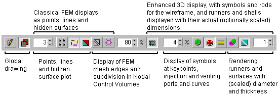
Located below the model, it contains buttons and edit controls that you can use to define the way
the model is displayed:

- redraw button to force a full redisplay of the model.
- Button to turn off-screen rendering on and off (useful for animations).
- Control 'classical' display of points, lines, surfaces and element edges.
- Buttons to control display of entities as 3D objects, runners are plotted as rods using their diameter, surfaces are displayed using prism elements.
- Edit controls to set the size of points in pixels, amount of shrinkage for element edges, and a scaling factor for plotting thickness of surfaces and diameter of runners.
home |
introduction |
requirements |
geometry editor
material and process data |
mesh generation |
pre- and postprocessing
file system |
calculation
© 1997-2022 Polyworx
![[home]](../asp/pwxpwx.gif)