
SIMULATION OF LIQUID INJECTION MOLDING
Delivering on the promise
The contents of this page were presented by Arjen Koorevaar as a paper at the SAMPE 2002 conference, at the JEC in Paris, April 2002.
Abstract
Simulation technology promises to reduce risks, and increase the possibilities for innovation. This not only requires that the software calculates fast and accurately, but that it is also easy to use by practitioners and that a lot of different alternatives can be investigated by virtual trial injections in short time.
In the RTM-Worx simulation package for Resin Transfer Molding and Vacuum Infusion, high accuracy (numerical error < 1%) and short calculation times (less than one minute) have been realized by the implementation of a mass conservative FEM/CV method (2.5 and 3D) and an iterative CG solver with SGS preconditioning. Calculation engine and a unified pre-/postprocessor (OpenGL graphics) are tightly integrated in a single native MS-Windows application for the PC. Size and complexity of the model is only limited by the amount of RAM available.
The predictive capabilities have been enhanced recently with the inclusion of:
- Gravity effects; especially important for Vacuum Infusion of large products.
- Effect of fabric deformation on permeability and porosity when the laminate is draped on doubly curved surfaces. For this purpose an interface with the MSC/Patran Laminate Modeler has been implemented.
Several examples of practical applications (both RTM and Vacuum Infusion in aerospace, automotive, marine and boat building) will be shown.
![[top]](../asp/tp.gif) Introduction
Introduction
The application of closed mould injection techniques like RTM (either with or without Vacuum Assistance), Vacuum Infusion - among which is the well-known SCRIMP™ (ref. 1,2) process - is growing rapidly. Advantages are relatively low initial investments, low material costs if compared to prepreg, limited styrene emissions (e.g. better working conditions), high fiber/volume content (the difference is especially large if Vacuum Infusion is compared to hand lamination) and high reproducibility. Basically, the process is very simple (quoted from [3]): Dry reinforcement is placed in a mould, the mould is closed and resin flows into the mould and impregnates the reinforcement. The driving force for the flow of the resin is a pressure difference.
One of the key ingredients to a good impregnation is knowledge of the flow behavior of the resin through the reinforcement. It is not simply a matter of finding the 'optimal' location of injection and venting ports, but the process should also be robust enough to deal with unavoidable variations in material properties and process conditions. While it is often sufficient to use trial and error methods to achieve a reasonable injection strategy, the risks and costs are too high to rely on a few experiments if expensive moulds need to be manufactured for large series (dormer roofs, automotive applications), or when the material costs are very high (carbon/epoxy 64' boat hull) and the first injection has to be right.
Flow simulation software (refs. 4,5,6) promises a solution. Doing trial injections and optimizations in short time without wasting materials before the mould has been made sounds very good! In spite of this, application of flow simulation software is still limited, most users are employed at universities and R&D centers of large companies. Based on experience with previously developed simulation codes (refs. 7,8,9,10) and application in several projects (refs. 11,12), the main goal in the development of the present RTM-Worx code was to decrease costs of installation, support and maintenance and make flow simulation software accessible for a much larger industrial audience. A fancy interface is useless when the basis has not been done right. Therefore, a lot of attention has been paid to development of the mathematical model and its implementation.
Mathematical Model
The flow of resin through a reinforcement is well described by Darcy's Law (ref. 13), which predicts a linear relation between the local flux density and the applied pressure gradient. With gravity terms included (very significant for vacuum infusion of large objects like boat hulls), Darcy's Law generalized to three dimensions and the continuity equation are:
| (1) |
| (2) |
Here, u is the local flux density (or superficial velocity), K is the permeability tensor, h is the resin viscosity, p is the pressure in the resin, rr is the (local) resin density and g is the gravity vector. Substitution of Darcy's Law (1) in equation (2) results in a formulation of the continuity equation where the only unknown is the pressure (a 3D scalar quantity) within the fluid in the mould:
| (3) |
In order to solve this equation, proper boundary and initial value conditions are needed for different regions of the mould cavity and it's boundary as indicated in figure 1.
A finite-element formulation using linear elements has been chosen (ref. 14). The advantage of linear elements is that the discretisation according to the Galerkin Finite Element method is exactly the same as the equations that result from a Control Volume formulation (see also the appendix). This allows the use of a very efficient flow front tracking method, the implementation is relatively easy (which is important because it eliminates the possibility of errors in the implementation of the element), provides sufficient accuracy and makes it possible to use a streamline-upwind formulation for the convection terms in non-isothermal reactive calculations. The resulting FEM/CV method as implemented behaves very predictable (e.g. using a larger number of smaller elements really increases accuracy of the solution) and does not suffer from instabilities due to spurious mechanisms.
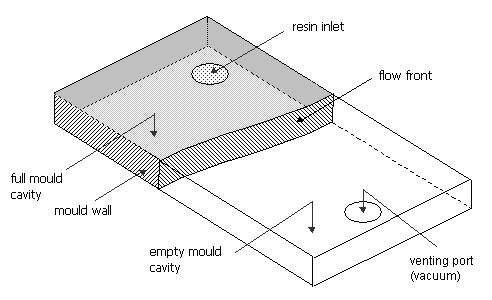
| Figure 1: | A mould cavity being filled, forming a domain with boundaries. |
The mould cavity is subdivided into a finite number of tetrahedrons, triangles (2D shell element with constant thickness) and runners (1D line element with constant cross-section of arbitrary shape). The elements are connected by their vertices, the nodes, and may share common triangular faces (tetrahedrons) and edges (triangles). For each nodal point j, a basis function wj(x) is defined by the following properties:
- wj(xi) = 1 if j = i; wj(xi) = 0 if j ¹ i; j, i = 1,¼,N
- wj has prescribed behavior in each element, in our case we assume linear behavior.
- wj is continuous on W
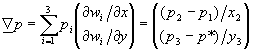
For the pressure an approximation is calculated which is a linear combination of the basis functions wj(x):
| (4) |
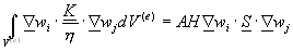
After applying the Galerkin weighted-residual procedure (ref. 16), introducing the linear approximation for pressure (4), equation (3) results in:
| (5) |
With
| (6) |
| (7) |
| (8) |
Where n is the normal vector on the boundary G. Because of the choice of the basis functions wi, the matrix components Aij are different from 0 only if node i and j lie in the same element. The matrix Aij and right-hand side vector fi can be assembled by calculating the integrals for each element separately and adding them to the system matrix.
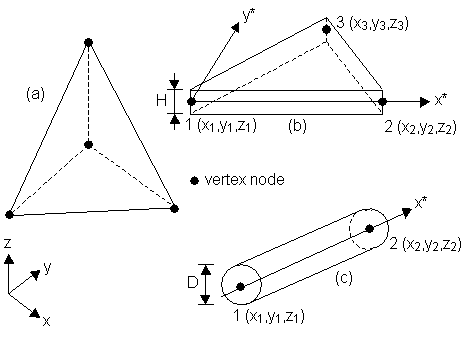
| Figure 2: | Basic element types available in RTM-Worx, (a) 3D linear tetrahedron, (b) 2D linear triangular shell and (c) 1D linear runner (tube); where x* and y* denote the local coordinates and (xi,yi,zi) the global coordinates. |
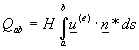
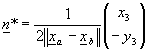
The right-hand side vector bi is zero where the boundary is closed (a so-called natural boundary condition); it is only non-zero in injection points, venting points and the flow front, where the pressure is prescribed, and injection points where the flow rate is prescribed. Equations for nodes where pressure is prescribed (which includes the part of the mould not yet filled with resin) can be eliminated from the system when it is solved for the pressures. It is easy to verify that bi contains the nodal residual flowrates, which is very convenient because a simple matrix multiplication after solution of the pressures is sufficient to recover the flow rates at the flow front.
Implementation
The position of the flow front is tracked by assigning fill factors to the nodes. Initially, all nodes are empty (f = 0), except the injection nodes. Pressures are calculated in completely filled nodes (f = 1), all partly filled nodes (0 < f < 1) make up the flow front. The pressure is prescribed to be zero in all nodes that are not yet completely filled: empty and front nodes. The calculation proceeds as follows:
- Calculate the residual flow rates at the flow front from the finite element equations (eqs. 5-8).
- Determine the time step: the largest time increment that can be taken and which will fill exactly one control volume.
- Advance the flow front, update fill factors, record nodal fill times (defined as the time at which f = 0.5) and adjust the boundary conditions at the flow front and at the injection/venting ports (which may change pressure and/or flowrate, open and close at specified times).
- Calculate new pressures (reassemble stiffness matrix if necessary).
- Check if the mould is completely filled (or if the end of the curing cycle is reached for non-isothermal reactive problems). If not, go to step 1.
The number of time steps during filling equals the number of nodes, because the time step is limited. It is not necessary (and does not increase accuracy) to take smaller time steps because the boundary conditions do not change.
If resin viscosity is constant and element properties do not change, it is not required to repeat assembly of the stiffness matrix Aij in step 4, which significantly reduces the calculation time. The progression of the flow front can be visualized by a line or color shaded contour plot of the nodal fill times. Alternatively, intermediate results can be shown with the flow front defined in elements where they are intersected by the line f=0.5, where the fill factors are linearly interpolated between nodal values.
For the solution of pressures from equation (5) a linear solver is needed. The matrix Aij is sparse, most of the coefficients are zero. While direct solvers (based on Gauss-Elimination) are very competitive in 2D problems, for 3D problems iterative solvers are preferred because they require less storage and much less work is needed per iteration. A very popular method - probably because it is so easy to implement - is Gauss-Seidel iteration or Successive Over Relaxation (SOR, ref. 16). However, convergence (e.g. speed) of this method depends a lot on the initial guess. The pressure solution from the previous time step often is a very good starting point; However, if boundary conditions are changed, or the front reaches an area in the mold where permeability suddenly changes (edge, leakage channel) a large number of iterations is needed and calculation times become excessively large (with such a solver, the technique used to model edge injection in part 5 could not have been used). Therefore, a more predictable iterative method is used: a Preconditioned Conjugate Gradient solver with - in this particular case - a Symmetric Gauss-Seidel preconditioner.
Fabric Deformation
Applying reinforcement material, woven or stitched, on non-developable surfaces requires the fabric to deform to follow the part geometry. The main deformation mechanism is shear. When a fabric shears, the area A of a square with side length b becomes:
| (9) |
Where q is the ply-angle, e.g. the angle between warp and weft directions. When the fiber/volume fraction in the undeformed state (q = 90 degrees) Vf0 is known, the fiber/volume fraction can be calculated as a function of the shear angle with:
| (10) |
The permeability is influenced strongly by variations in fiber/volume fraction. To take this into account, the Kozeny-Carman equation (ref. 4) can be used:
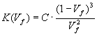 |
(11) |
The constant C can be calculated from a known permeability value K0 in the undeformed state where the fiber/volume fraction is Vf0:
 |
(12) |
The model used to calculate the (2D) permeability tensor for various shearing angles is based on the assumption that the permeability can be decomposed along the warp and weft directions. The separate contributions are combined in the effective permeability tensor by a simple addition rule. Shearing defines the rotation of the permeability tensors for weft and warp directions. Physically this model most closely resembles biaxial or non-crimp fabrics which are composed out of layers of UD reinforcement that have a transverse permeability that is negligible in comparison with the axial value. Generally, the effect of shearing on permeability will be exaggerated by this model, especially for woven fabrics. Because the fiber/volume fraction change has a much larger effect on permeability, this model will suffice in most cases.
The model (eqs. 9-12) has been implemented as part of an extension to RTM-Worx to read results of draping simulations from other software packages, like the MSC/Patran Laminate Modeler other draping software.
Numerical Accuracy and Calculation Time
In order to assess the accuracy, convergence and calculation time a comparison has been made with analytical solutions for two different cases (also typically used to measure permeability's):
- Edge injection of a strip
- Point injection of a circular mould.
| Mould dimensions | Fiber reinforcement properties | ||
|---|---|---|---|
| Thickness H [m] | 0.005 | Permeability [m2] | 6.8*10-10 |
| Strip: length L [m] | 1.0 | Porosity [%] | 40 |
| Strip width W [m] | 0.2 | Injection parameters | |
| Quarter disk inner radius r0 [m] | 0.01 | Resin viscosity [Pa.s] | 0.1 |
| Quarter disk outer radius R [m] | 0.1 | Pressure difference [Pa] | 105 |
| Table 1: | Parameters used in simulations: injection of a strip and a quarter disk. |
The injection time for edge injection of a rectangular strip with length L and constant pressure difference Dp is given by (ref. 15):
| (13) |
Because the pressure gradient is constant, it can be reproduced exactly by the element shape functions. Therefore, the filling time is predicted exactly even if the strip is meshed with only two triangles. In figure 3, the result from the simulations is shown for a mesh with 80 triangular elements. Edge injection is modeled using a runner along the edge which has very low resistance (k = 10-6) and negligible resin content (Vf = 99%).
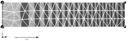
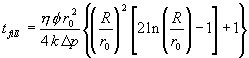
| Figure 3: | Injection of rectangular strip (see table 1 for parameters used), increment between shaded contours is 7 seconds. Filling time is 294 seconds. |
The filling time for point injection can also be obtained analytically (ref. 15):
 |
(14) |
With the parameters from table 1, the theoretical filling time tfill = 5.32 seconds. Results from the simulation are shown in figure 4 and listed in table 2.
On a 1.4 GHz Athlon Thunderbird with 512 MB DDR/SDRAM, the simulation of the injection of the quarter disk with 2114 element took 11 seconds. For all the other simulations, the calculation time is less than one second on the same PC.
| E [-] | tN [s] | error [%] |
|---|---|---|
| 80 | 5.22 | 1.9 |
| 152 | 5.28 | 0.8 |
| 482 | 5.34 | 0.4 |
| 2114 | 5.33 | <0.2 |
| Table 2: | Simulation results from injection of a quarter disk. E is the number of triangles, tN the predicted filling time. |
| Figure 4: | Simulation results for injection of a quarter disk (152 triangles). Time increment between shaded contours is 0.125 seconds. |
Conclusion
The flow simulation model and its implementation as described in this paper have proven to be very robust, reliable and fast in practice. Users of RTM-Worx do not need a lot of time to learn the software and need very little support. The FEM/CV method has been used to implement the non-isothermal reactive extension module (released in 2001). But it would be too easy to say that we completely achieved our goals. A lot of development is being done to add features to RTM-Worx. Two major bottlenecks need to be solved: (1) translation of (arbitrary) CAD geometry to models suitable for flow simulation and (2) accurate measurement and availability of material properties, most notably the permeability.
References
- W.H. Seemann, US Patent 4,902,215 (1990).
- W.H. Seemann, US Patent 5,052,906 (1991).
- A. Hoebergen, E. van Herpt, M. Labordus, Proc. 20th Int. SAMPE Europe Conf., Paris, La Défense, April 13th-15th, 1999, p. 237-246.
- Michiel V. Bruschke, PhD thesis, University of Delaware, August 1992.
- M.V. Bruschke and S.G. Advani, Polymer Composites, Vol. 11, No. 6 (December 1990), p. 398-405.
- F. Trochu, R. Gauvin, D.-M. Gao, Adv. Polymer Techn., Vol. 12, No. 4 (1994) p. 329-342.
- C.W.M. Sitters, PhD thesis, Eindhoven University of Technology, 1988.
- Lucien Douven, PhD thesis, Eindhoven University of Technology, June 1991.
- A. Koorevaar, 7. Int.Techtextil Symposium 1995, Lecture No. 338.
- A. Koorevaar, 2èmes Journées RTM, les 5 et 6 Juin 1997 à l'ISITEM à Nantes.
- A.S. Verheus and J.H.A. Peeters, Composites Manufacturing, Vol. 4, No. 1 (1993) p. 33-38.
- F.N. Scott and A. Koorevaar, Proc. of the Int. Symp. on Advanced Materials for Lightweight Structures, ESTEC, Noodwijk, March 1994 (ESA-WPP-070), p. 335-339.
- C.L. Tucker III and R.B. Dessenberger, in Suresh G. Advani (ed.), Flow and Rheology in Polymer Composites Manufacturing, Elsevier, Amsterdam 1994, Chapt. 8, p. 257.
- V. Wang, C.A. Hieber and K.K. Wang, J. Poly. Eng., 7, 21 (1986).
- B.R. Gebart, P. Gudmundson, D.Y. Lundemo, 47th Ann. Conf., Comp. Instrc., Soc. Pl. Ind., February 3-6, 1992, Session 16-D, p. 1-8.
- O.C. Zienkiewicz, The Finite Element Method (3rd ed.), McGraw-Hill, 1977.
Appendix: Triangular Shell Element
In this appendix, some aspects of the formulation of the triangular shell element as it is used in RTM-Worx are detailed to show the equivalence of the finite element and control volume discretisation and to explain why the FEM/CV method has been chosen in RTM-Worx. Special attention is paid to the issue of mass conservation, that has been raised by a few authors and have led to alternative formulations (ref. 4) or the choice of non-conforming (less accurate and more expensive to use) elements (ref. 6).
The analysis will be carried out in local 2D element coordinates without loss of generality, because only the dimensions of the element are relevant and the local coordinates are easily transformed to 3D global coordinates. The basic assumption in the application of the thin shell element is that the pressure gradient in thickness direction is zero on the element. This means that Darcy's Law, equation (1), also reduces to two-dimensional planar flow.
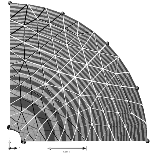
| Figure A1: | (a) Triangulation with highlighted node and its associated Control Volume and (b) nodal basis function wI on elements where it is non-zero. |
The triangular elements, connected by their nodal vertices, together form a surface without any overlap or gaps. The pressure is interpolated linearly on the elements; therefore the pressure gradient is constant on each element and discontinuous at the element edges. Each triangle is subdivided by joining the midpoints of its three edges to its centroid. The control volume associated with a node is then defined as the union of all subdivided volumes that are connected to that node, as shown in figure A1(a). Like the elements, the control volumes span the entire computational domain without overlapping.
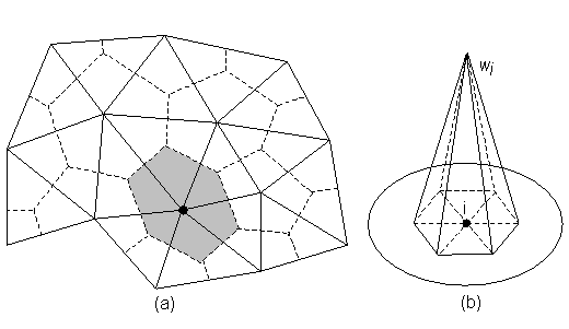
A local 2D coordinate system is defined according to figure A2. The origin is in node 1 and the x-axis coincides with the 1-2 edge of the element. The shape functions on the element become quite simple (x1 = y1 = y2 = 0, 2A = x2y3):
| (A.1.a) | |
| (A.1.b) | |
| (A.1.c) |
The derivatives of the shape functions wi in element coordinates are given by:
| (A.2.a) | |||
| (A.2.b) |
| Figure A2: | A linear triangle shell element with local coordinates. |
The integrals of the matrix components (contribution of this element) can now be calculated easily because the derivatives of the shape functions are constants:
 |
(A.3) |
With a rule of mixtures for the permeability that follows naturally from the integration over the volume:
 |
(A.4) |
Note that this is not necessarily equal to the quotient of averaged permeability divided by the averaged viscosity! The pressure gradient on the element is constant:
 |
(A.5.a) |
With
| (A.5.b) |
Because the pressure gradient is constant, the flux density is constant too according to Darcy's Law (1). Therefore, if we want to calculate the flow across an arbitrary through-thickness cross-section in the element, all that matters are the endpoints of the line along we integrate. As an example, the flow across the line a-b is calculated (see figure A2):
 |
(A.6) |
With the normal defined as (follows from geometry of the element):
 |
(A.7) |
we find that
| (A.8) |
Comparison of equations (A.3) and (A.8) shows that the finite element discretisation and the control volume formulation - where the net flow into a nodal volume is calculated by integrating along the boundary of the control volume - is exactly the same! This is not a new result, it is known since beginning of the eighties (ref. 14). For the approximated pressure field, mass is conserved exactly both in each element and in each node. As a consequence, the solution is guaranteed to converge to the exact solution if the mesh is refined. The actual definition of control volumes, i.e. how elements are subdivided, does not influence convergence, and only slightly affects accuracy.
![]()
home |
abstract |
introduction |
mathematical model |
implementation
fabric deformation |
accuracy and speed |
conclusion |
references
appendix: triangular shell element
© 1997-2022 Polyworx
![[home]](../asp/pwxpwx.gif)